
Axidraw + Processing
- julienv3ga
- Jan 18, 2020
- 8 min read
Updated: Feb 22, 2020
Prerequisite
This tutorial is addressed to people who have basic knowledge of the Processing environment and who are familiar with structures like variables, functions and loops. It will also cover the manipulation of objects instances through the creation of controls thanks to the ControlP5 library.
You can refer to the following tutorials by Daniel Shiffman from his Coding train Youtube channel online to get the basics of Processing. Here is the list of software used in this tutorial :
The source code for this project can be found on github, it includes :
The repository also contains the code that was used to generate the illustrations for this article.
Purpose
We are going to create a tool to generate geometric forms that are based on a simple set of rules involving a combination of 2D transformations and repetition. The resulting forms will be then printed with the axidraw pen plotter.
The system will have some numeric values (called parameters) that we can tune on predefined ranges to explore the spectrum of forms that can possibly emerge from our system. This tuning will be manually done through a graphical interface and we will have an option to export to SVG vector format.
An important note is that we will be able to use only functions that can draw 2D primitives, with no filling. Remember that the axidraw pen plotter can only draw lines and points, so we will restrict ourselves to use these geometric components. Also, we will use only one color for rendering.
Idea
Our starting point will be a low-resolution polygon, made of points distributed on a circle. We will use a custom predefined function that takes as input the number of points and its radius.

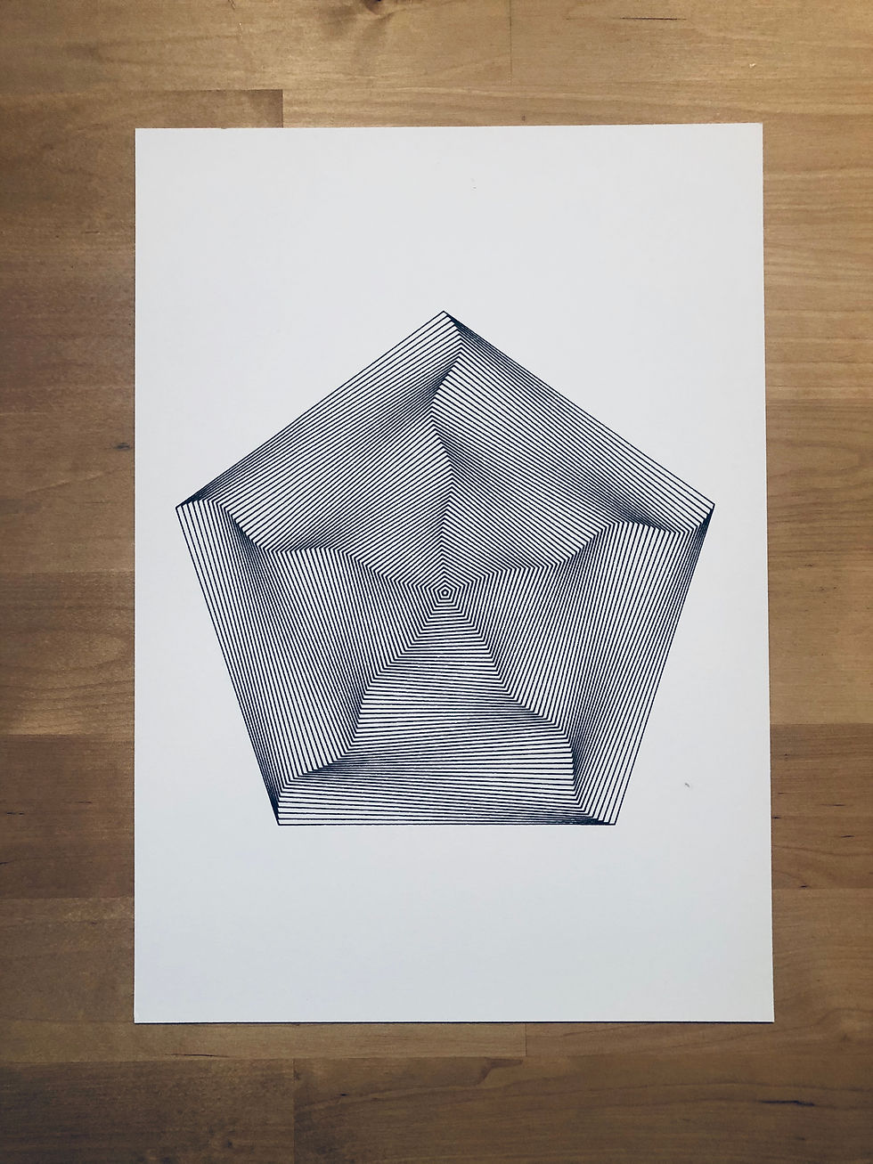
The drawing of the polygon will be repeated a number of times while scaled-down and rotated by using a loop. Here are a few examples that were produced with the tool.

The main idea behind generative art is to think in terms of process and not necessarily only in terms of the final image you want to create.
Let’s get coding
When I start a new generative project for the Axidraw pen plotter, I always begin with the same Processing sketch. While reading this article, I suggest you open the code in another tab to be able to follow the code explanations.
Setup & draw
There you find the setup() et draw() function implementations that allow us to run our Processing application in continuous mode, which means that the main window frame will be redrawn again and again.
Exporting to SVG file
The processing SVG library is imported (via the command import processing.svg.*) , so the functions beginRecord() and endRecord() can be used. Every drawing command placed between these two functions will be recorded to a file, whose name is passed as a parameter for the beginRecord() function. Speaking of the exported file, I always used the timestamp() utility function (borrowed from Generative Gestaltung sketches) to name it so the exports will have a unique name, no matter how many times I run the application.
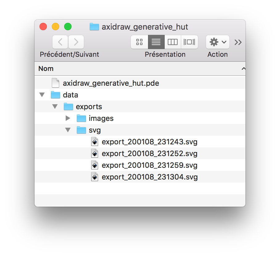
The boolean variable bExportSVG is used to trigger the recording of the drawing command when set to true. It is set to true when the user presses the key ‘e’, that’s why the keyPressed() method was implemented. Note the moment when the variable is set back to false, so we are sure that the pair beginRecord() / endRecord() is called just once and not continuously during the sequence of draw() calls. If the folder data/exports/svg does not exist, it will be created automatically by Processing inside the sketch folder, which is accessible from the menu Sketch > Show sketch folder.
Finally, notice that the background() function is called before the record begins while stroke() / fill() options are set to match the constraints criteria we discussed previously, that is to say, no filled exported shapes, only strokes.
We are all set up to begin drawing geometric forms and for this purpose, we are going to use a custom function named circle() and defined as follows.
We are going to define some variables that will set the parameters of our drawn forms. Having variables defined before the setup() allows us to quickly modify their values in an iterative process instead of having to tweak “hardcoded” values directly into the program. We will see that it is also convenient because ControlP5 allow to bind controls to variables in an easy way, thanks to a technique called introspection. Let us define a bunch of variables, with explicit names.
This variable will be directly passed as the first parameter to the circle function. It will be set later by a slider with a minimum and maximum value.
This variable defines the number of times that our parametric circle will be drawn, using a for loop. It will also be controlled by a slider.
Those two variables will control the range for the radius of our parametric circles. Inside the for loop, these two variables will be used with the map function to make the radius varying linearly from radiusMin to radiusMax as follows.
These two variables will be later controlled by a range controller.
We are going to make each of the forms rotate around its center. The more natural and simple way to do this would be to have a rotation depending linearly on the number of forms drawn. Instead, we are going to make the rotation oscillate between a minimum and maximum angle, set respectively to -angleRotation and angleRotation. The number of oscillations will be parametrized by the nbWaves variable, and we will use a sinus waveform.
Interface setup
We are going now to add controls linked to parameters. Before that, we need to install the ControlP5 library, which is a well-known library among Processing developers because of its clear code interface, its numerous examples and its simplicity thanks to its introspection features. You can install it with Sketch > install library interface.

Once the library is installed, we can import it in our sketch with the following command.
First of all, we are going to declare a ControlP5 variable (called cp5 to comply with ControlP5 examples), which is going to hold the interface context and will be used to create control instances.
Then, I usually define a initControls() method in my sketch to put all the code related to interface creation, and in particular the creation of the ControlP5 instance itself and the controllers' instances. Notice that we disable the autodraw feature of the ControlP5 instance. Why? Because we want to control when the controls are drawn in the window, and particularly we want them to be drawn after the export is done so that they are not rendered in our .svg file.
Sliders
A slider can be associated with a float or int variable. For example, let’s see how we can associate a slider with the variable nbPoints that controls the number of points of the drawn circles.
The name passed to the addSlider() method has to be the name of the variable. By a mechanism called introspection, ControlP5 will look for a variable nbPoints in your sketch. Thus, any user input with the slider will automatically modify the value of the variable nbPoints, which in turn will affect the rendering.
Once the slider is created, we can customize it by adding a range (minimum and maximum values) with setRange() and also the number of ticks ( steps ) if the variable is an int with setNumberOfTickMarks() method. We can set its position with setPosition(), its size with setSize() and also its label with setLabel(). I defined the local variables wSlider and hSlider in the initControls() method so to have the same size for all the sliders in the interface. x, y variables are used to position the sliders. Finally, when creating the control, we initialize it with nbPoints via the method setValue() to reflect the initial value.
We are going to perform the same initialization with the variables nbForms, nbWaves and angleRotation. The only thing that is changing compared to nbPoints is the minimum and maximum values that are applied with the setRange() method when creating the sliders instance.
Range Sliders
A range control is the same as a slider control except you can associate two variables. This is ideal for setting the radiusMin and radiusMax variables. The main difference with the “simple” slider is that it is necessary to define a callback function to set the values of both variables at once.
ControlP5 has a standard function that is called whenever any created control instances are modified because of user interaction.
The callback controlEvent() is defined as follows. The function receives a ControlEvent object storing information from the control that the user interacted with. We simply check the name of the control from which the event was emitted.
Exporting
That’s it! We are ready now to begin experimenting with our tool and explore the combinations of parameters. You can export as many forms as you want. Creative coding is all about trial and error. Let’s see now how we are going to plot a generated file with Inkscape.
Plotting
Open Inkscape and load one of the forms you generated with the Processing tool. Remember, the exported files are placed into the data/exports/svg folder of the sketch.
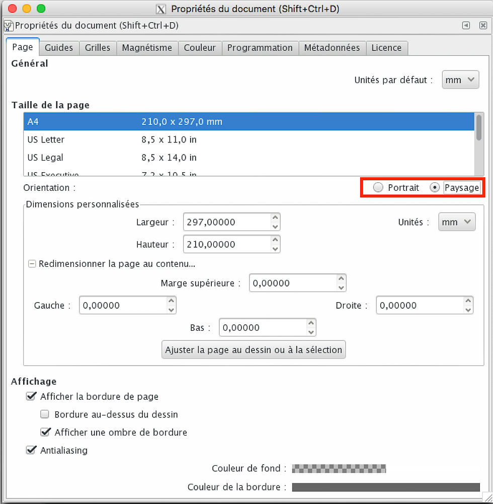
Setting the paper size
The first thing I always do when opening a new file is setting the document size, so it matches the paper size I want to print on. In this example, we are going to print on standard A4 format. One important note is that the paper must be oriented in landscape mode (paysage mode in the interface below highlighted in red). The document properties window can be opened with Shift+Ctrl+D shortcut.
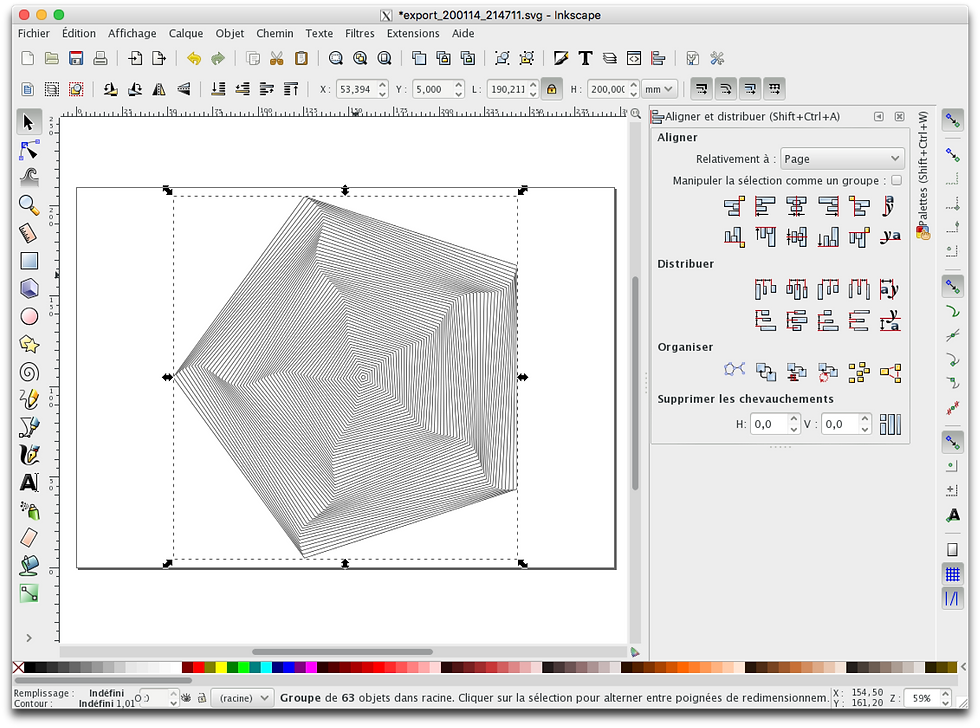
Positioning and scaling the form
Once the document is set to the right size, we can adjust the form inside the document. Note that you can also import other forms if you want and make a composition by placing the forms inside the document. For the moment we are going to plot just one form, and we are going to scale it and center it so it fills a big part of the document. You can directly use the text edits just above the form or scale it with the mouse. I always use the align tools to align the form to the center of the document.
Printing !
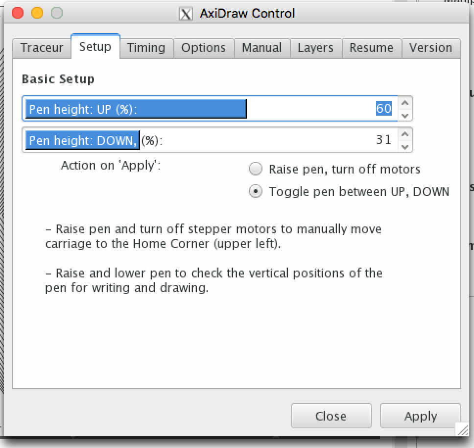
We are now ready to print our generated form. You can open the axidraw extension interface from the Extensions > Axidraw menu.
The first action is to “Raise pen, turn off motors” in the setup tab so that you can place the origin of the axidraw with the upper corner of your paper. Then you can adjust the position of the vertical position of the pen with the “Toggle pen between UP, DOWN” option. The setup interface lets you adjust the pen height and pen down properties too.
Once you are all set up, you can go to the first tab and then click on the apply button. The Axidraw should start printing!
If you want to tune some axidraw parameters (speed of the motors when the pen is up or down for example), I advise you to refer to axidraw wiki and most notably the axidraw user guide where you will find numerous tips.
Voila! Share your generative art prints with us with hashtag #generativehut
About the author
Julien Gachadoat was raised in the Atari ST demomaking culture from the late 90’s, the Avant-Garde scene who generated visual pieces using computer code. Since then he uses programming languages as an artistic creation tool. He's been regularly plotting with the axidraw machine, exploring black and white lines compositions productions by algorithms.
Co-Founder of the 2Roqs interactive design studio, he also teaches programming using open source platforms (Processing, Openframeworks) at the Bordeaux Montaigne University in Art and design and animates regularly workshops in France and abroad.
He shares code on his github account, axidraw prints on instagram and a few thoughts & links on twitter. He also has a website not maintained anymore at www.v3ga.net.
__________________________________________________________________________________
If you like what you're reading, make sure to follow Generative Hut on Instagram for daily inspiration from the wider generative artists community.


7c 777 showed up while I was scrolling a discussion, so I opened it out of curiosity to see what the page looked like. I didn’t dive deep into the content or anything, but the layout was easy to get the hang of right away. The first thing that stood out was how the main areas are separated into clear blocks instead of everything being jammed together, so you don’t feel lost when you move around. I also liked that the info boxes with numbers details are set up in neat columns, which makes it way quicker to skim without your eyes bouncing all over the place. The menu placement feels obvious without being in your face, and hopping between…
KING88 hôm bữa thấy mấy đứa bạn nói qua nên mình cũng bấm vào nghía thử cho biết thôi. Mình không có ngồi tìm hiểu sâu hay chơi gì, chủ yếu xem cách họ làm giao diện ra sao. Cảm giác đầu tiên là nhìn khá gọn và đỡ bị “ngợp”, kiểu mọi thứ chia thành từng mảng rõ ràng nên lướt nhanh vẫn theo kịp. Mình để ý cái menu điều hướng đặt khá dễ thấy, bấm qua lại mấy mục không phải lần mò nhiều. Với lại mấy khung thông tin trình bày theo cột nhìn sạch sẽ, chữ không bị dính sát nên đọc lướt cũng ổn. Nói chung mình chỉ cần vậy là thấy dễ dùng…
https://888b.soccer/ dạo này thấy mọi người nhắc hoài nên mình cũng bấm vào xem thử cho biết thôi. Mình không có ngồi tìm hiểu sâu hay làm gì nhiều, chủ yếu lướt qua coi trang nhìn ra sao. Cảm giác đầu tiên là bố cục chia thành từng khối khá thoáng, nhìn một cái là biết phần nào nằm ở đâu, không bị nhồi chữ kín mít. Mình cũng để ý mấy đoạn thông tin trình bày kiểu cột/bảng nhìn gọn gàng, nên lướt nhanh vẫn nắm ý chính chứ không phải căng mắt đọc từng dòng. Nói chung thao tác chuyển qua lại ổn vì menu đặt dễ thấy và các khối nội dung trên trang tách bạch rõ…
Looking for a reliable Carrier Transicold starter motor 25-39476? ATS Auto Parts stocks this high-quality aftermarket unit in Winnipeg, ready to ship fast across Canada — because your refrigerated load can't wait.
OK365 mình lướt thử vì thấy bạn bè nhắc, kiểu vào xem giao diện có dễ dùng không thôi. Ấn tượng đầu là trang nhìn khá thoáng, các khối nội dung tách bạch nên mắt không bị “ngợp”, kéo xuống cũng dễ theo dõi. Mình để ý họ có mấy bảng thông tin trình bày theo cột gọn gàng, nhìn cái là nắm được ý chính chứ không phải đọc dài dòng. Menu đặt ở chỗ dễ thấy nên chuyển qua lại nhanh, mình dùng trên điện thoại vẫn bấm ổn, không bị lệch hay rối. Nói chung cảm giác họ làm cho người mới vào đỡ mất thời gian tìm thứ mình cần, và phần bố cục theo block…